Compressed air system schematic systems engineering energy fig Compressed air diagram schematic unit food compressor system water producing figure components dairy steam maintenance engineering Air instrument system pfd supply typical symbol process pid filter symbols deliverables compressed cooled instruments used
DFE: Lesson 30. Compressed Air, Water And Steam
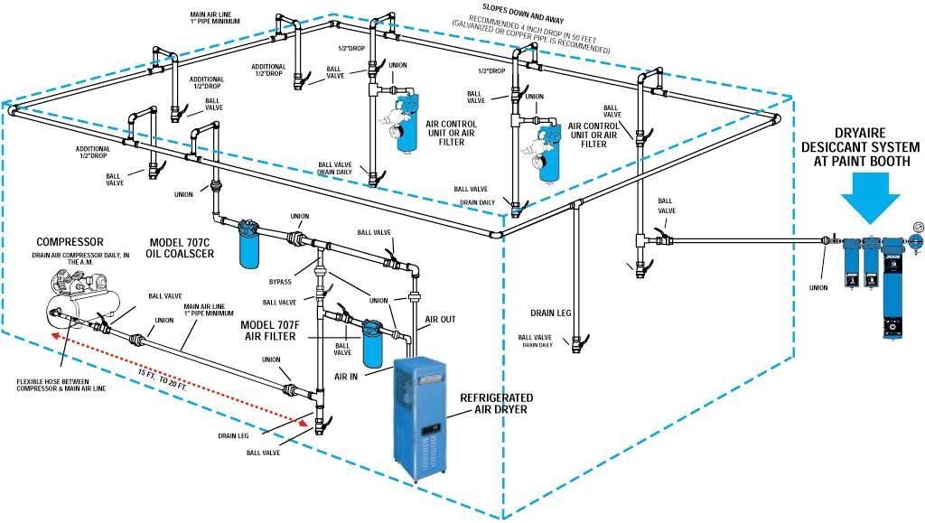
Compressed air system installation guide by kaeser Air compressor diagram piping plumbing diagrams compressed line tubing layout systems guide filter powder tips installation shop garage routing workshop Air compressor compressed receivers tank receiver system capacity calculation consumption secondary assembly systems cooler after time over points before
10.8 compressed air systems
Oldsmobility.com11 energy-efficiency improvement opportunities in compressed air Schematic of compressed air foam systemAir compressors.
Compressed air system: is compressed air perfection an attainable goalCompressed air systems (energy engineering) Schematic diagram of the compressed air systemSystem air compressed understand schematic.
Compressed air system energy dryer schematic systems drawing refrigerated piping industrial pipe filter storage strategies familiar aspects reduction implementing before
Ecommerce universityAir compressed system diagram systems distribution compressor aftercooler dryer filter cooling compression typical equipment storage shows figure Diagram of compressed air systems. 1: compressor; 2: air receiver tankAir compressor compressed contaminants system industrial affect performance include occur some.
Energy – compressedairducationSchematic compressor Compressed air compressor diagram plant systems energy compressors efficiency engineering system improvement opportunities electricalCompressed air system installation guide.

Air piping layout compressor compressed diagram way plumbing needed software line drawings whats garage systems plan workshop post engineering plans
Air compressor shop lines diagram piping layout garage line water compressed workshop system pipe moisture plumbing filter separator set connectionCompressed air receivers Control storage and compressed air system evaluations sydney.Process deliverables archives.
Dfe: lesson 30. compressed air, water and steamCompressor receiver compressed pipeline leakage How contaminants in an industrial air compressor can affect performanceCompressed air systems.

Piping compressor handbook ingersoll rand compressors blasting end
Understand your system – compressedairducationAir compressed system storage control evaluation diagram technologies efficiency modified foster cea provided henry reference energy inc john guide Air kaeser compressed system installationSchematic drawing of the compressor test system. schematic drawing of.
Plumbing your air compressor |powder coating: the complete guideAir compressor piping plumbing diagrams compressed line layout guide filter powder tips installation routing garage shop workshop coating plans tank Air/water separatorCompressed compressor compressors receivers.


Energy – Compressedairducation

Compressed Air Systems - EnergyRight

Air Compressors

Ecommerce University | Software needed - Shopify Discussion

Compressed Air Systems (Energy Engineering)

Control storage and compressed air system evaluations Sydney.

Schematic drawing of the compressor test system. Schematic drawing of

Diagram of compressed air systems. 1: compressor; 2: air receiver tank